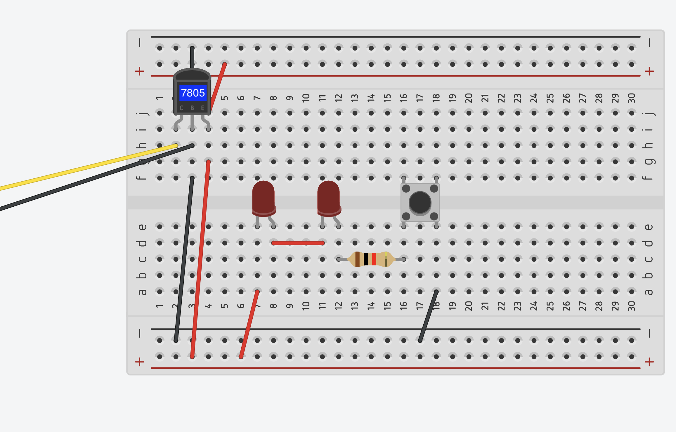
- Setting up the breadboard with controller
(+)Red side of the column : Voltage bus
(connect to voltage on controller – second from the top)
(-)Blue side of the column : Ground bus
(connect to gnd on controller – second from the bottom)
- Setting up the breadboard with controller and dc power supply
While keeping the wires in the same position as they were with only the microcontroller, connect dc power’s (+)*yellow wire* next to ‘vin-‘ very bottom / (-)*black wire* next to ‘gnd’
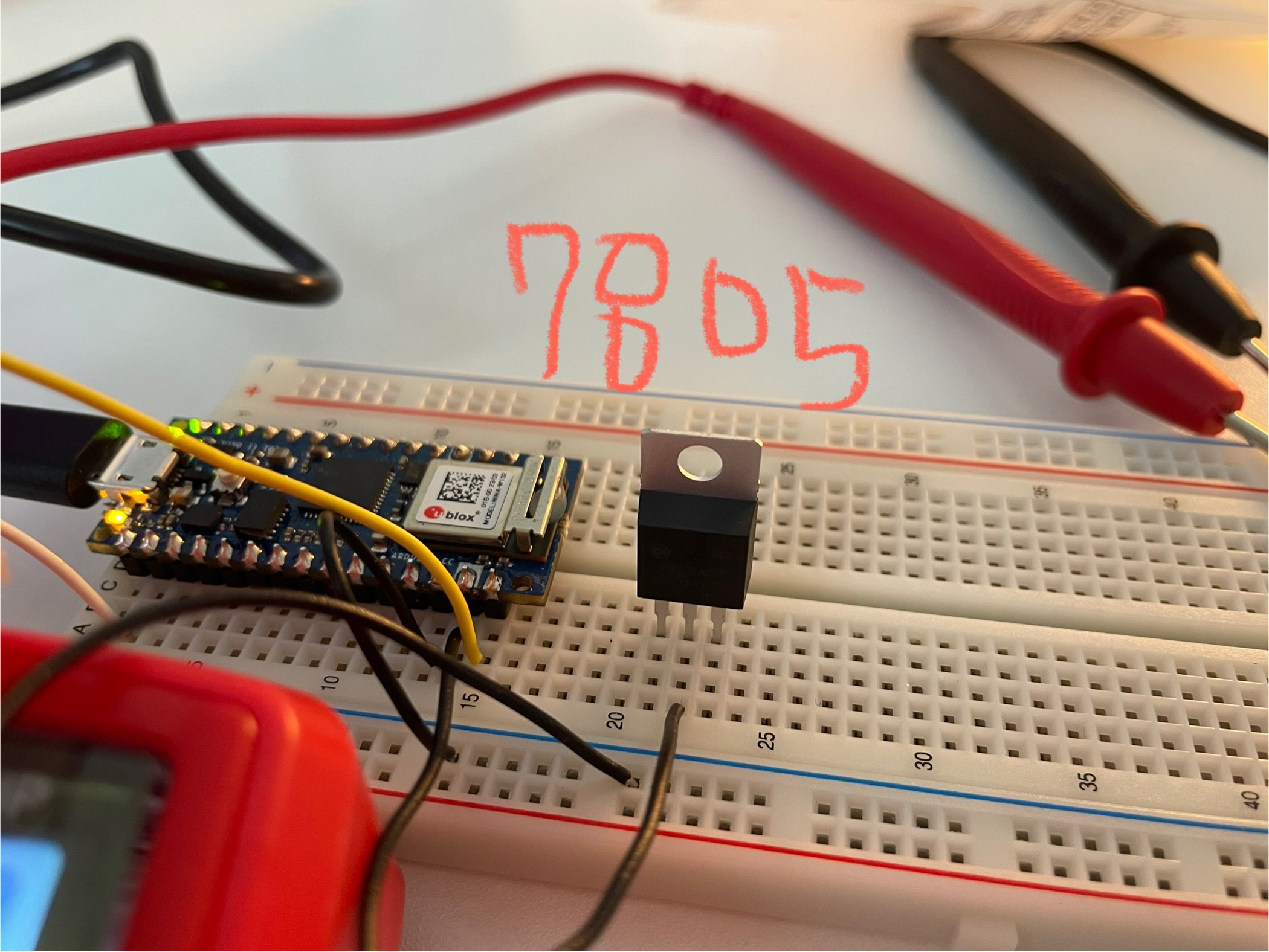
The Arduino board operates at 3.3V or 5V, but a DC adapter typically supplies 7–21V. Therefore, 7805 voltage regulator acts as a safeguard.
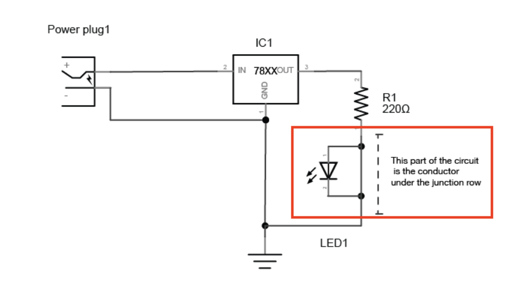
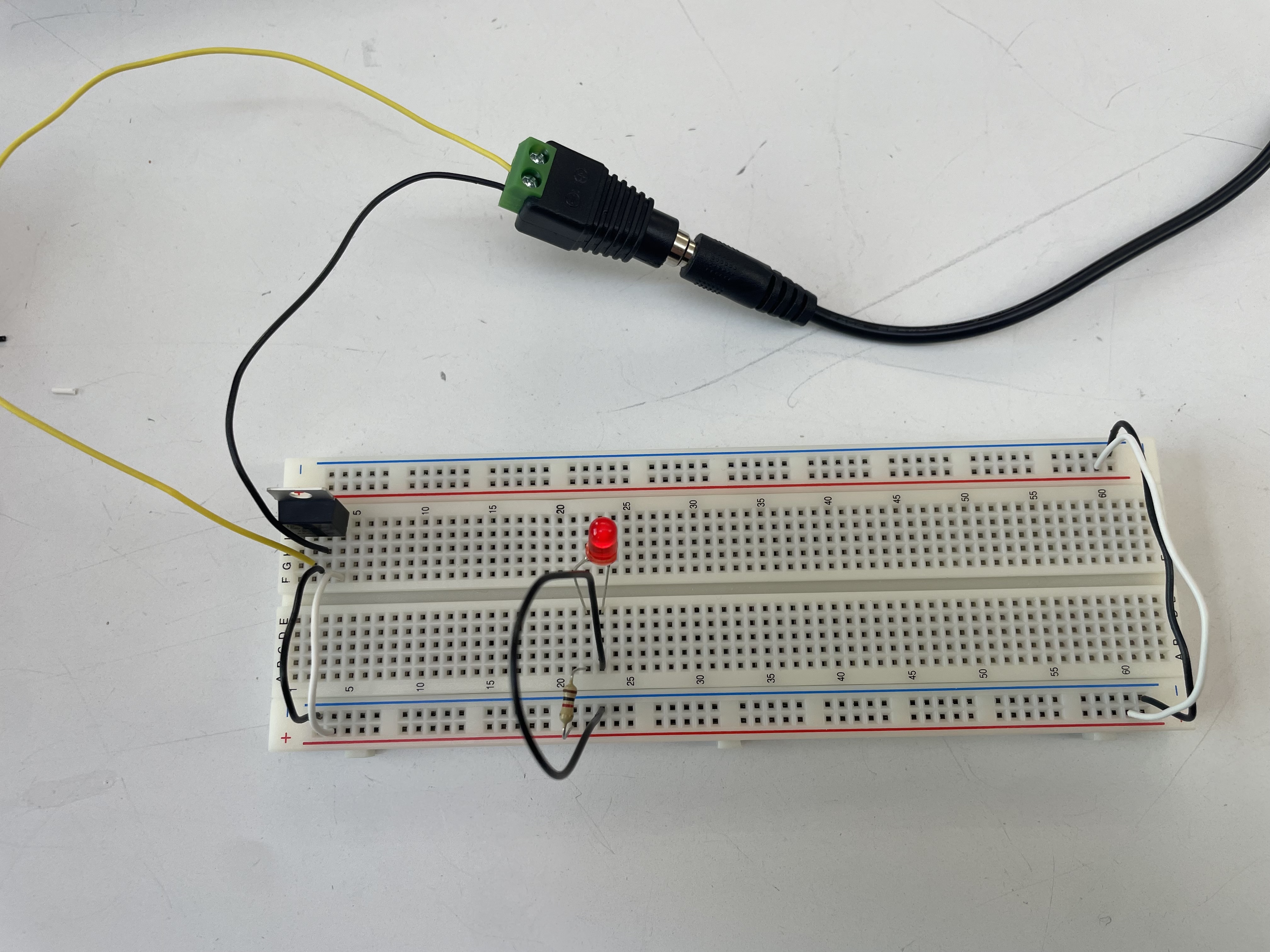
- Powering a volt without using microcontroller (+led light💡)
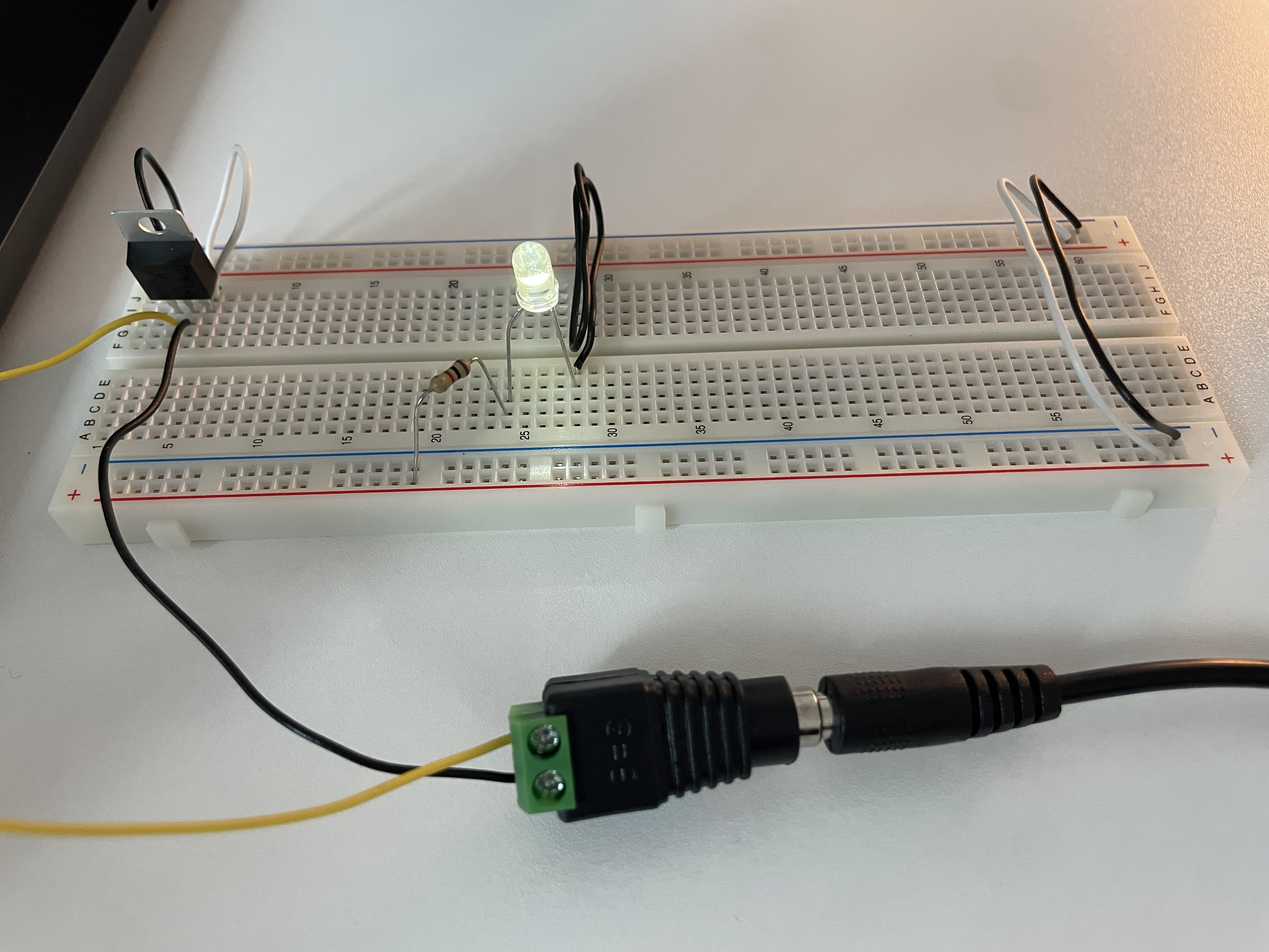

Use a voltage regulator to supply power from a DC adapter. In this case, the 7805 regulator provides a stable 5V DC output.
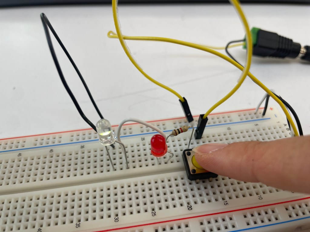
To light up an LED, connect one end of a resistor to the + column and the other end to the anode (+) of the LED. The cathode (–) of the LED should then be connected to the ground rail.
There are different ways to wire the LED, but it is always important to include a resistor to protect it from excessive current.
- Incorrect connection of the led light
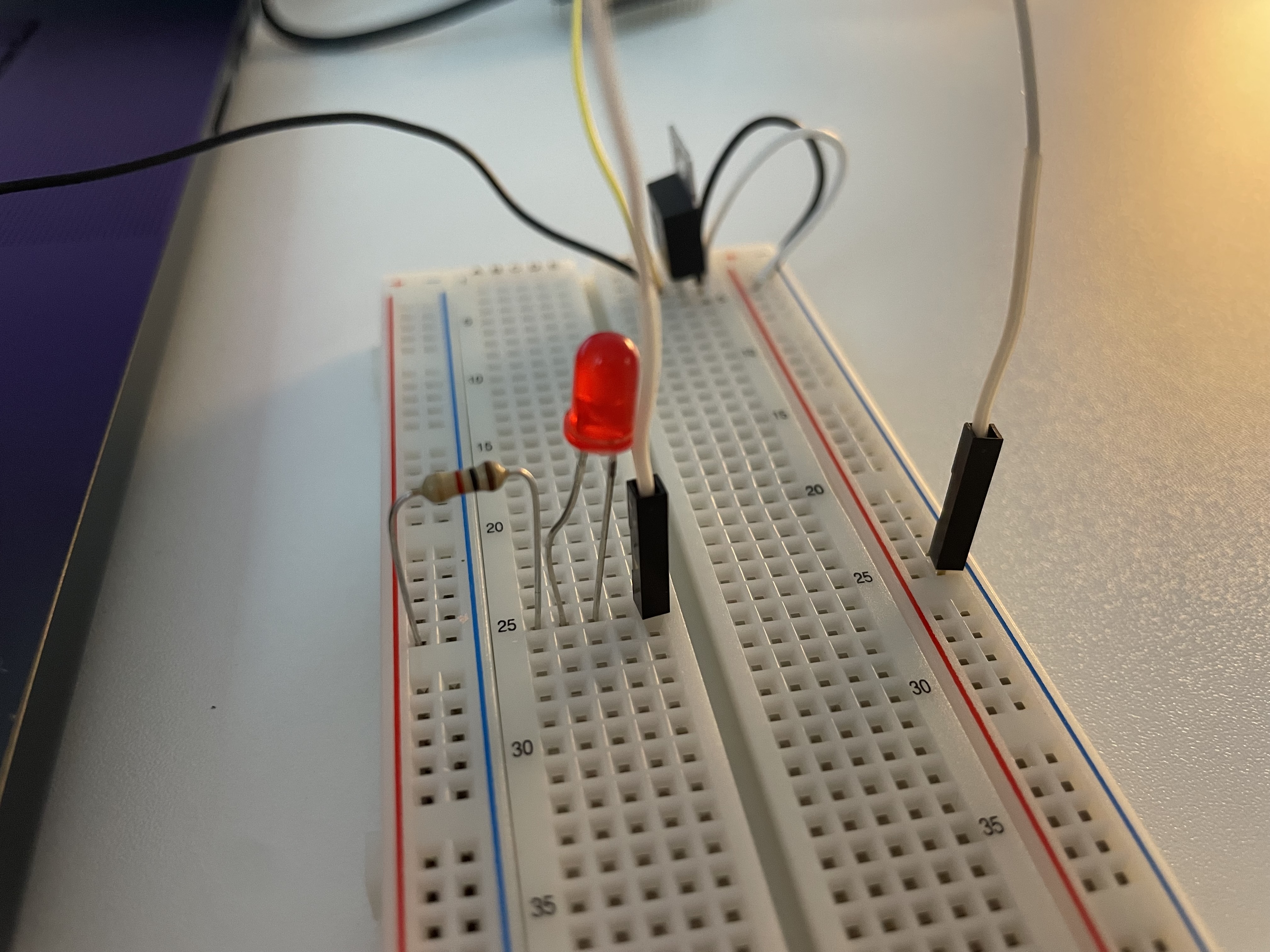
When the led’s legs are placed at the junction row, it is bypassed and will not light up
*Always place the two legs of a component in different rows on the breadboard.
Correct way: each leg of the LED must go into a different electrical line.
For example, one leg in a row and the other in the power rail
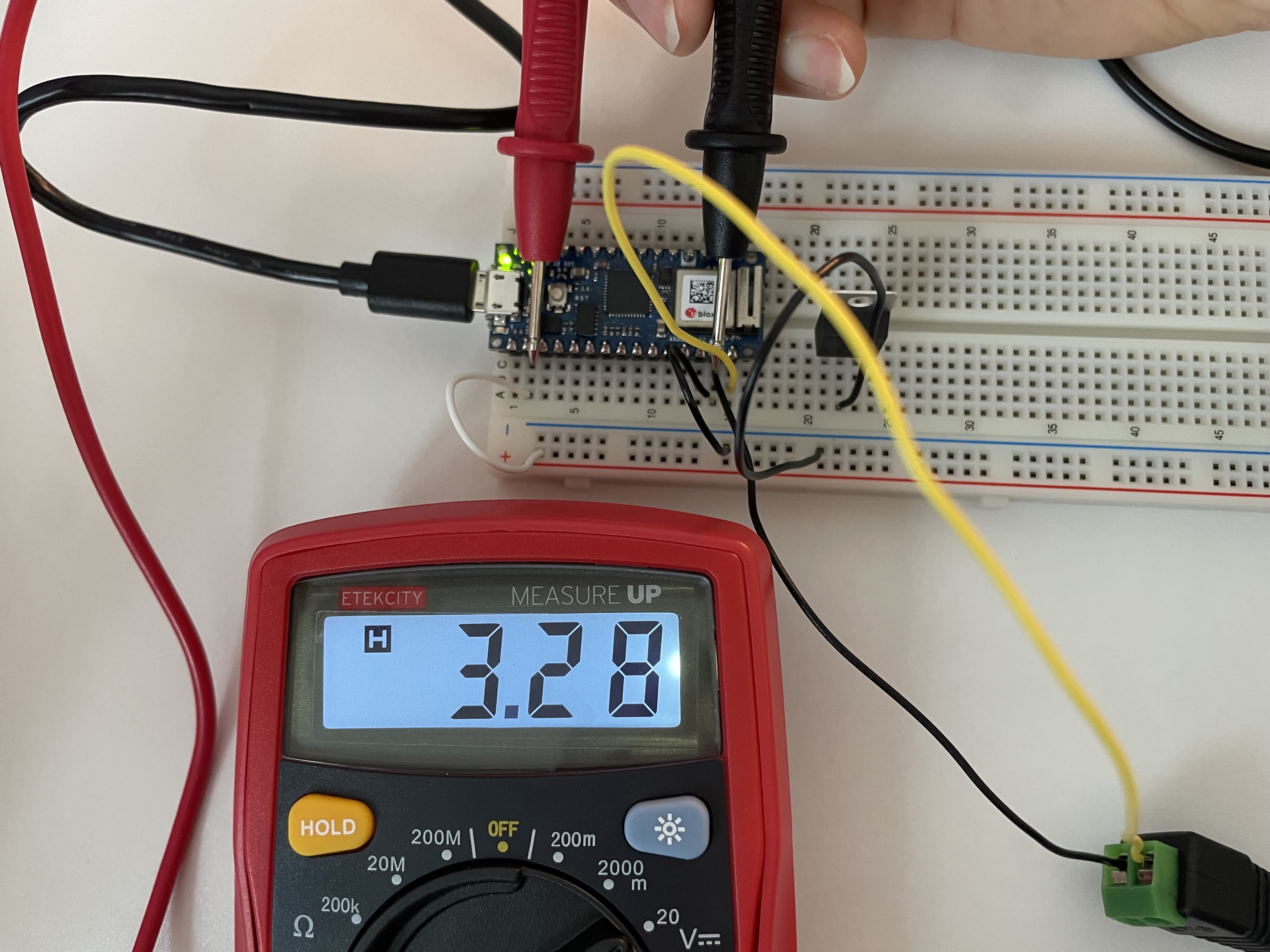
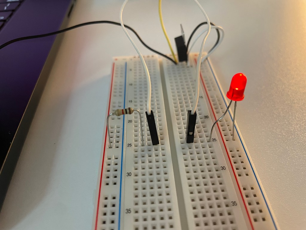
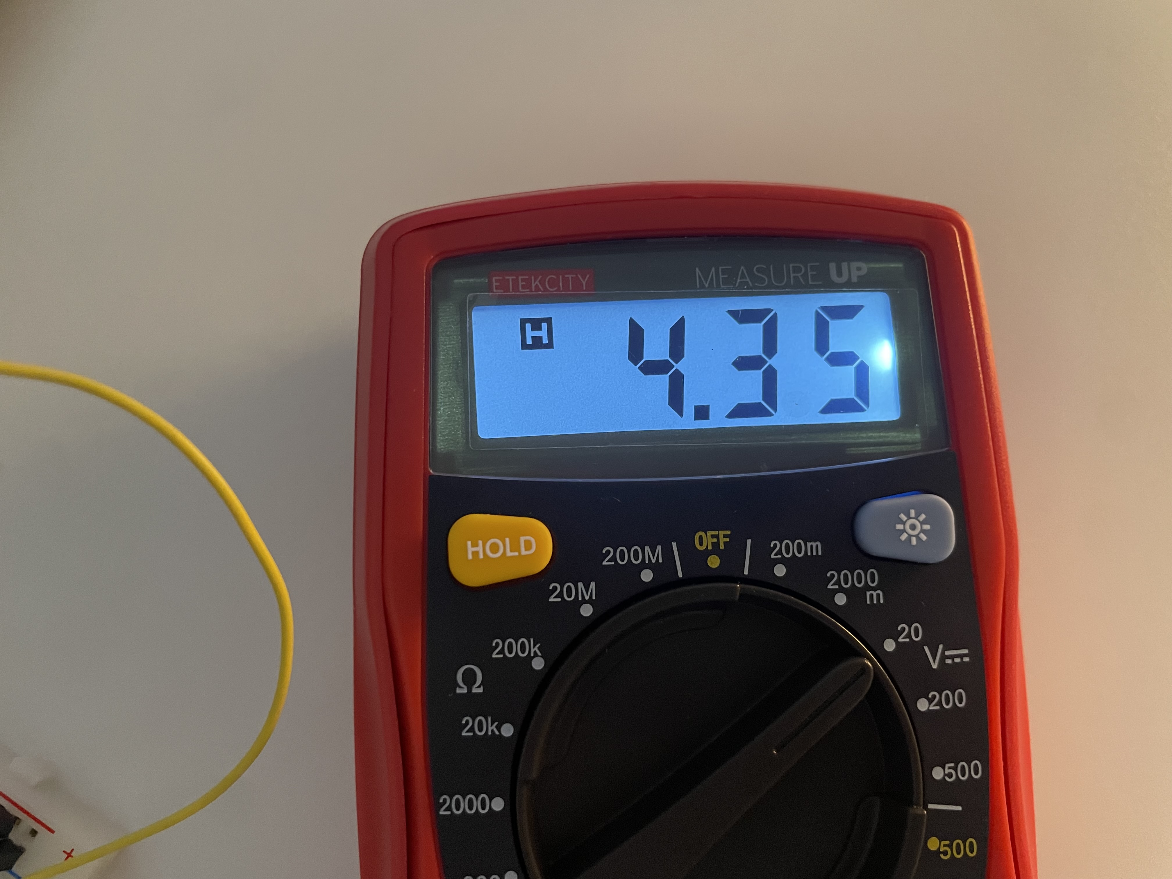
- Using Multimeter
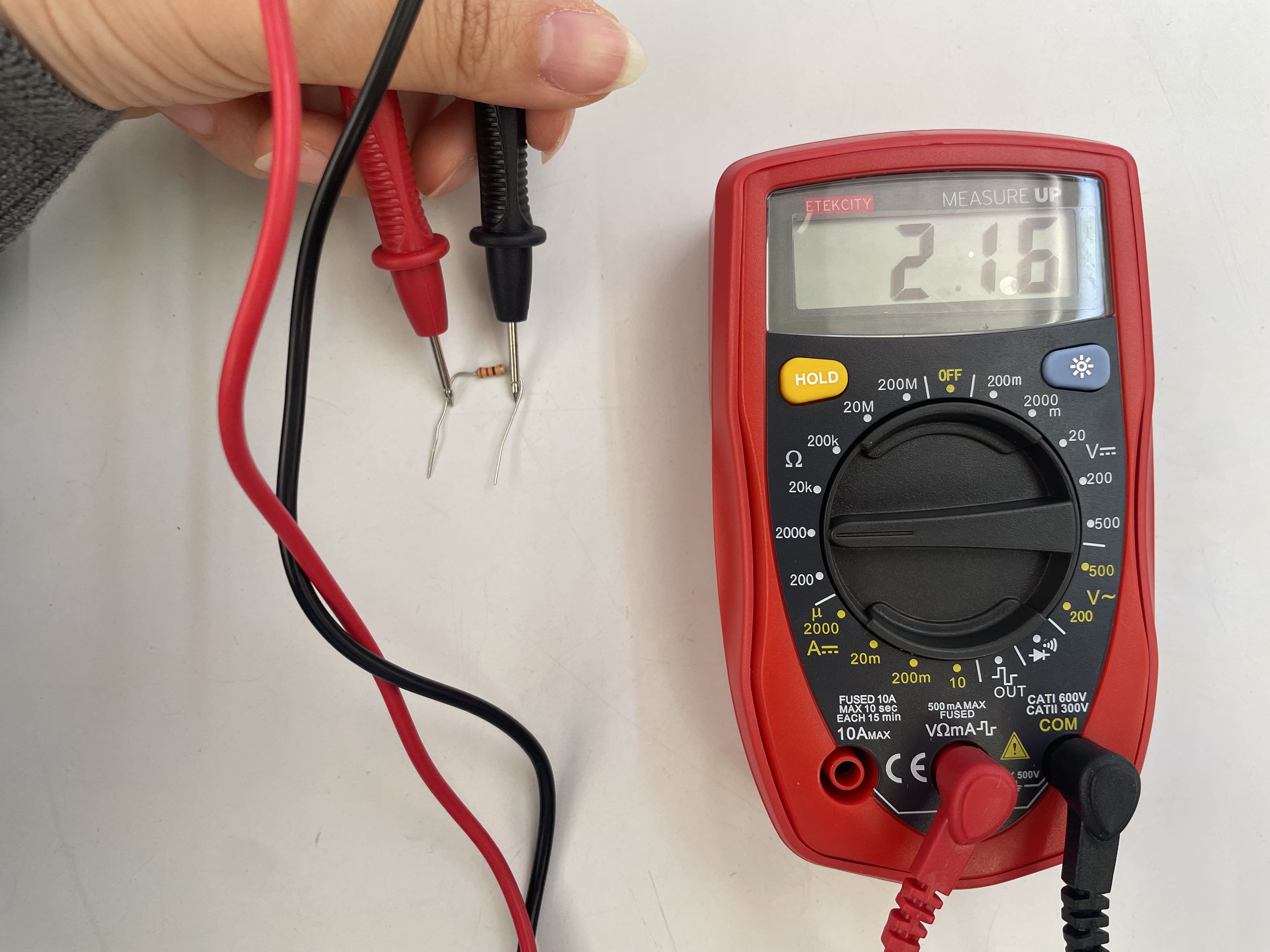
The black lead goes into COM, and the red lead goes into VΩmA
You can measure volts, ohm(resistance), amps(current)
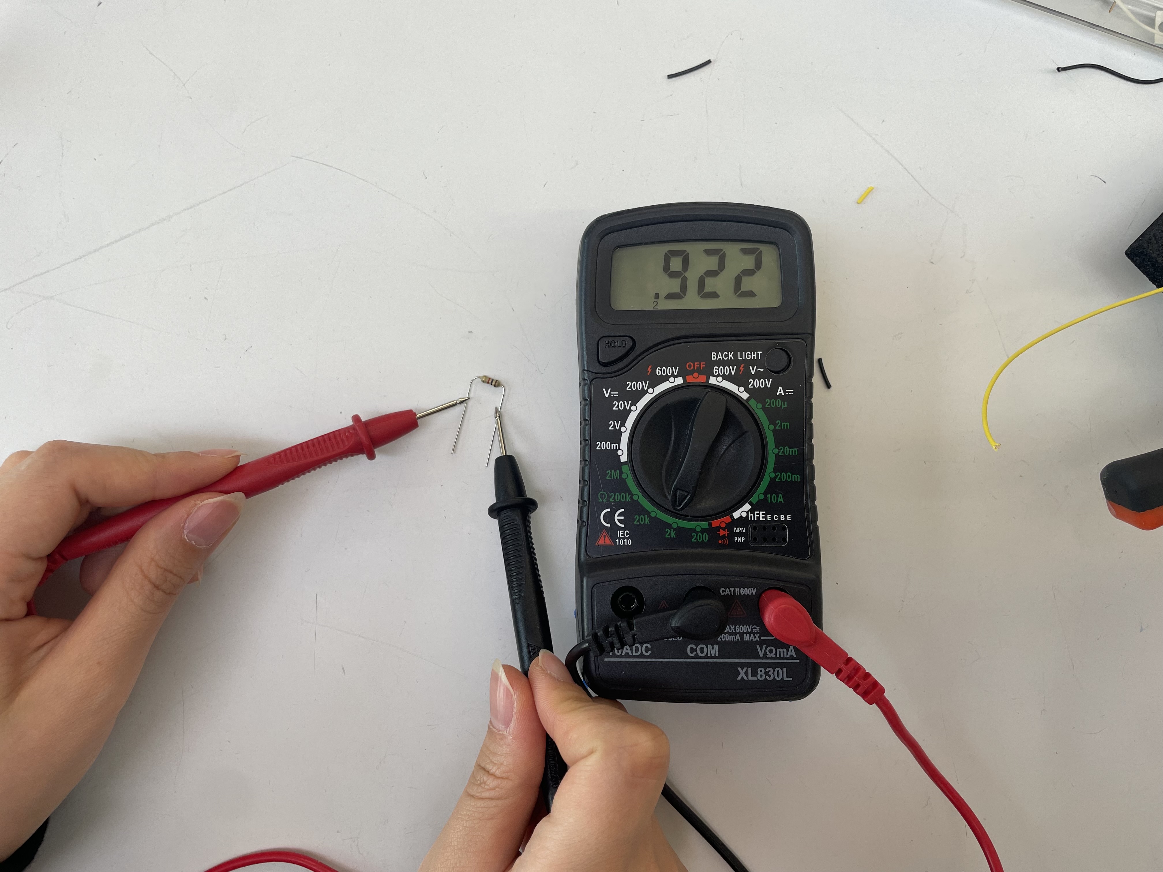
I measured my resistor and got about 922Ω. It was safe enough to light up the LED.

The order of the LED and the switch in the circuit does not matter, as long as they are connected in series. What really matters is the polarity of the LED: the anode (+) must go to the positive side of the power supply, and the cathode (–) must go to ground.
Adding up Voltage ↓
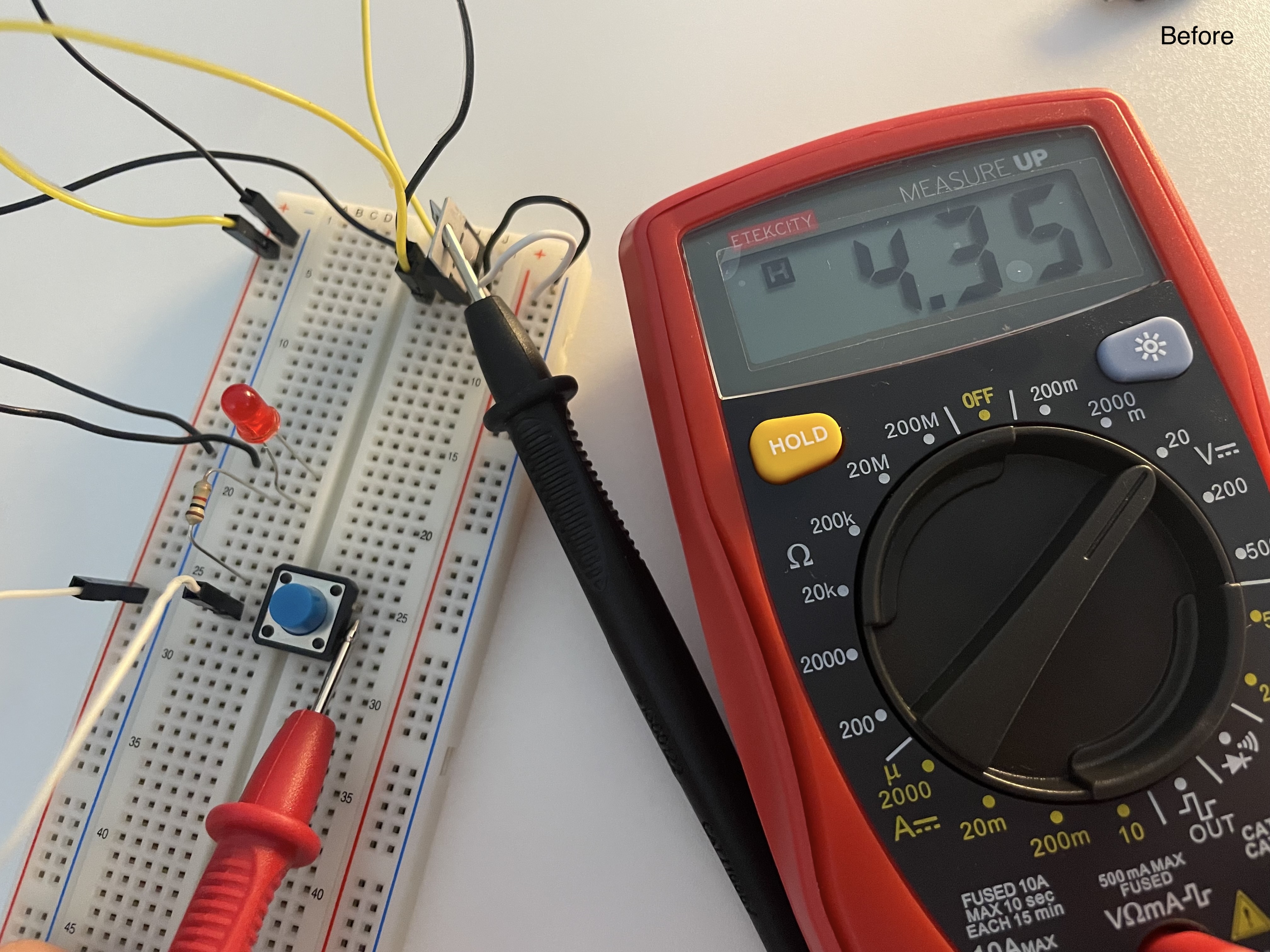

These are the images of the voltage measured before and after pressing the switch. The voltage dropped from 4.35V to 3.85V. I guess the drop is due to the LED and resistor consuming the voltage.
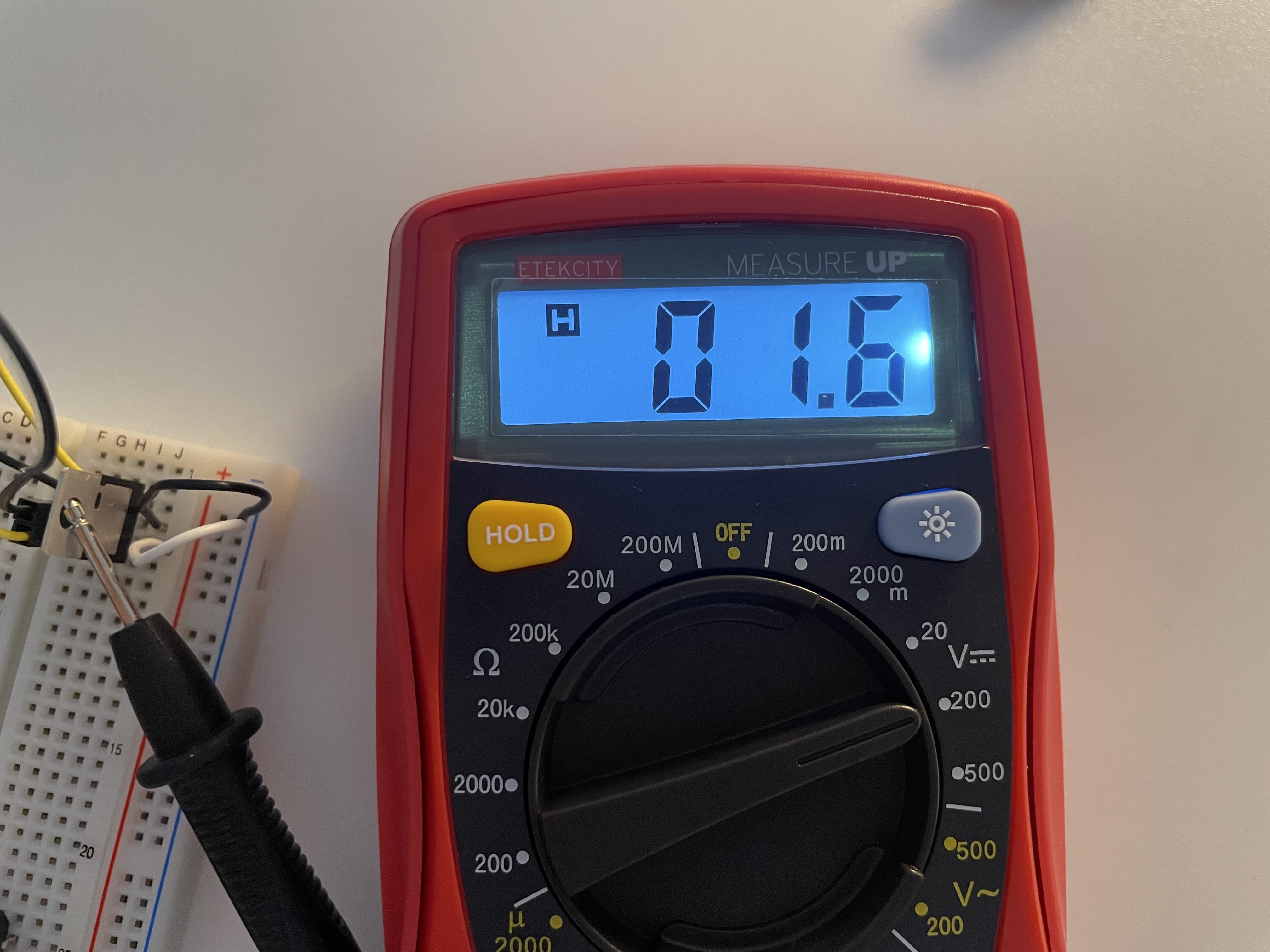

The left image is a voltage measured for LED, and it came out as 0.16V. It seems like it is a low reading.
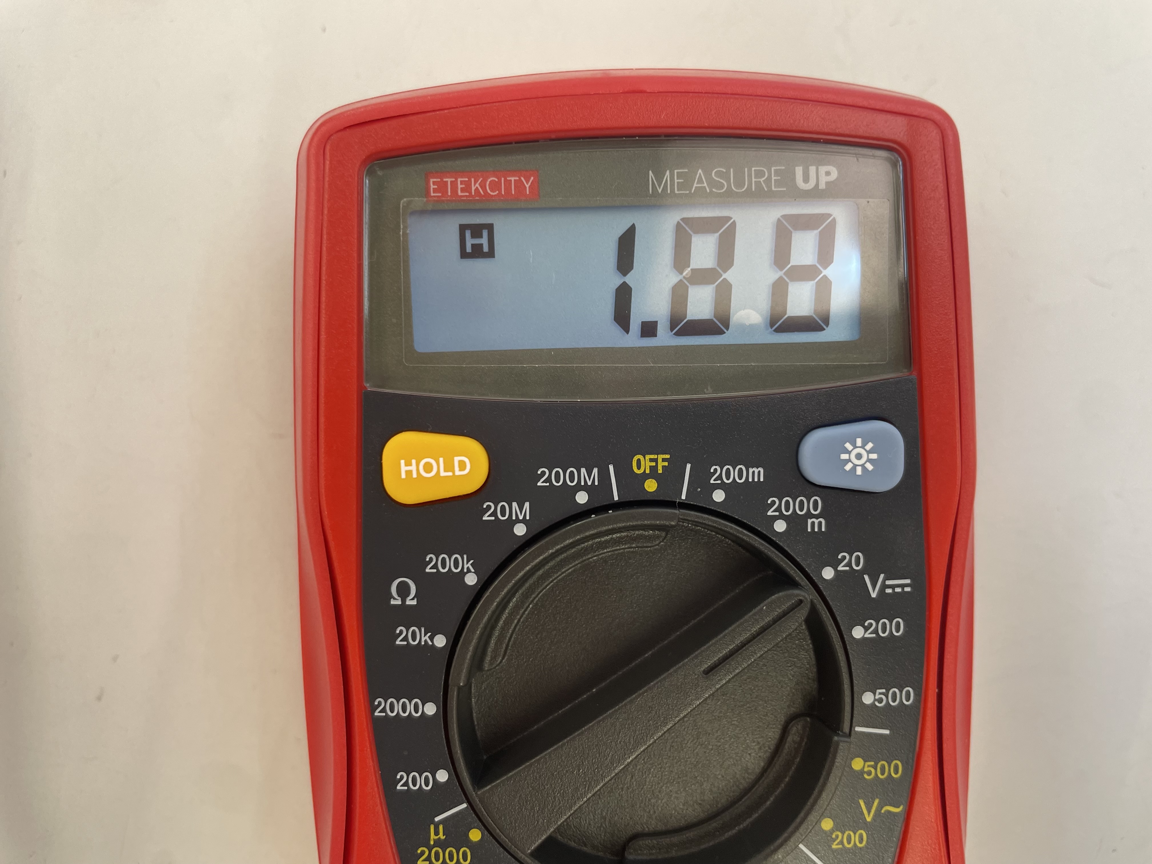
I tested again with 220Ω resistor and got 1.88V from LED light.
Q: If the total reading dropped by 0.5 V when the circuit started conducting, why does the LED itself read only 0.16 V? Could it be related to the 922 Ω resistor I used?
- Component in Series
At first, when I tried to follow the schematic view with the red and white LED light. However, when I pressed the switch, only the white one turns on the red one did not work at all. The issue happened because the red and white LEDs have different forward voltages?
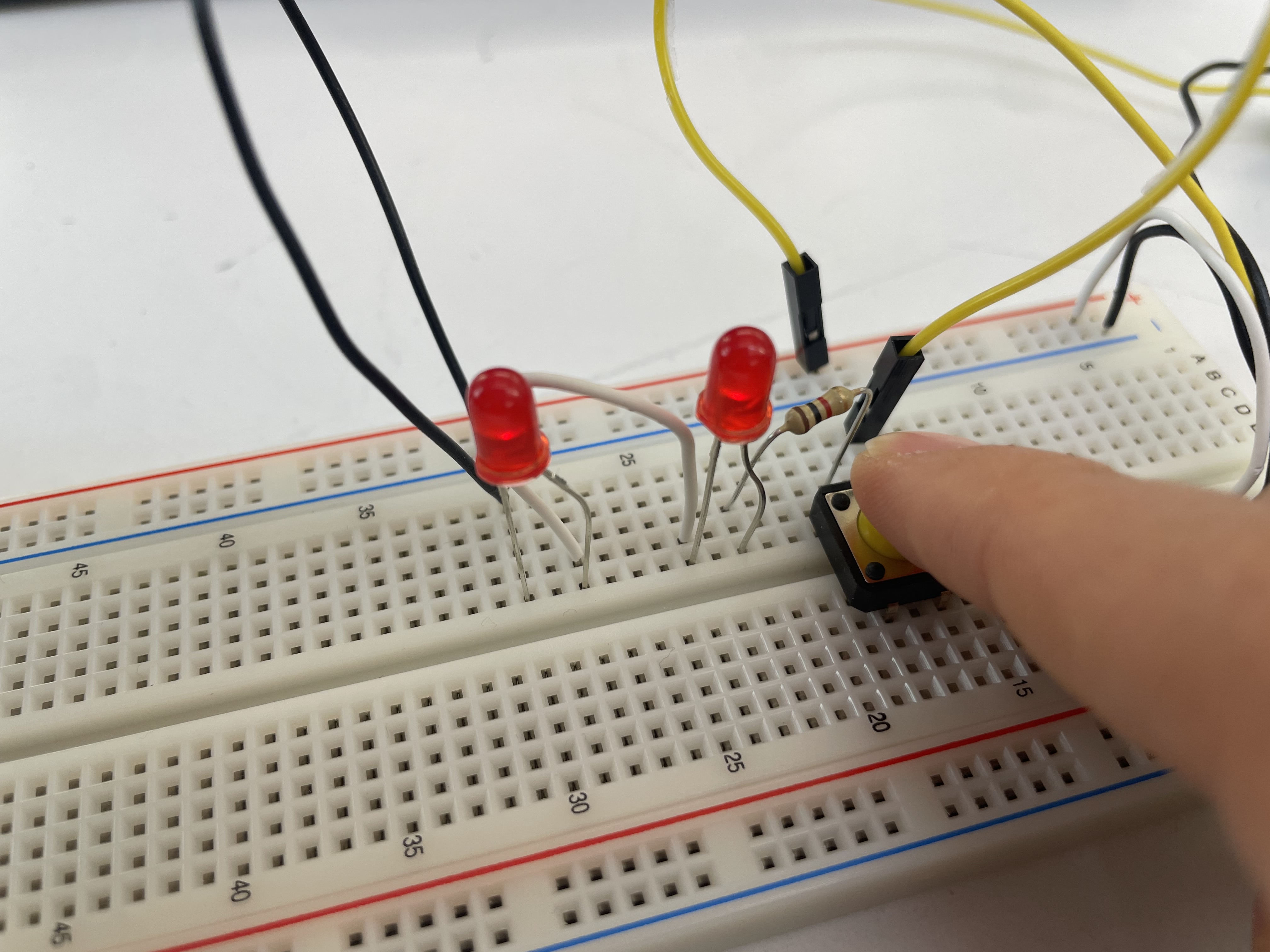
After I replaced the white LED with another red LED, both red LEDs lit up.
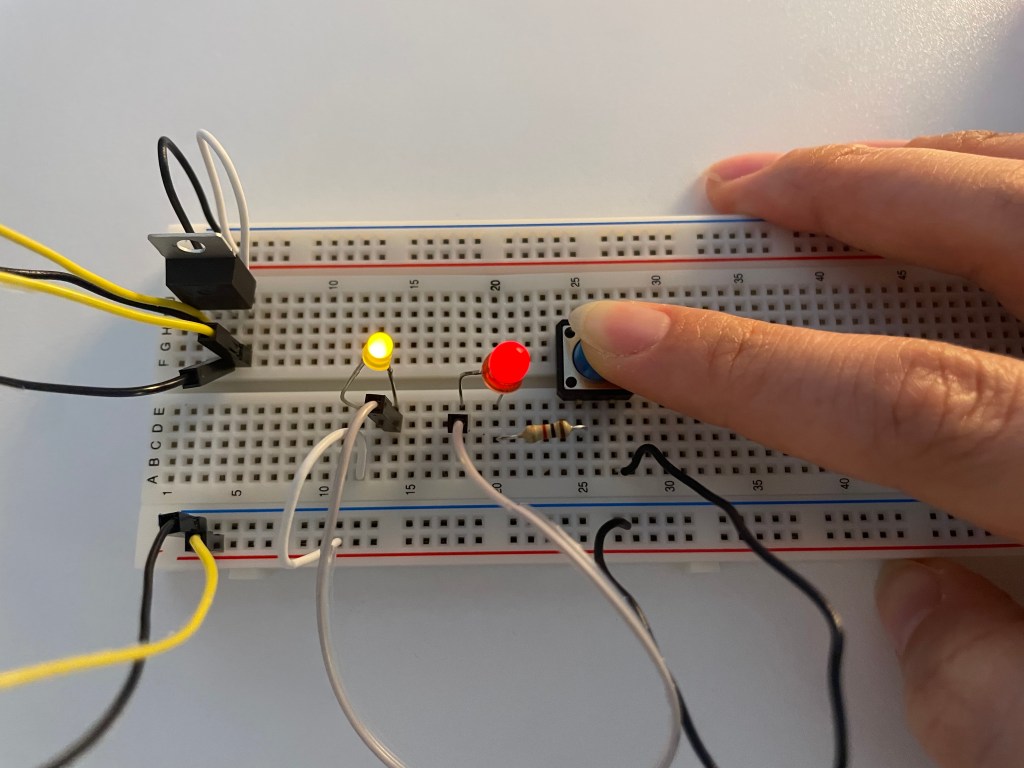
Red + Yellow LED works well in series
Q : What would the schematic look like to light up LEDs of different voltages in series?
Q : In my understanding, when LEDs are connected in series, the voltage goes through them in order, so I thought the first LED would get the most voltage and so on. However, when I tried an experiment with blue and red LEDs, no matter which order they were placed, only the blue LED lit up brightly while the red one was almost off. Why does this happen? Why doesn’t the order matter in this case?
Measuring Voltage↓
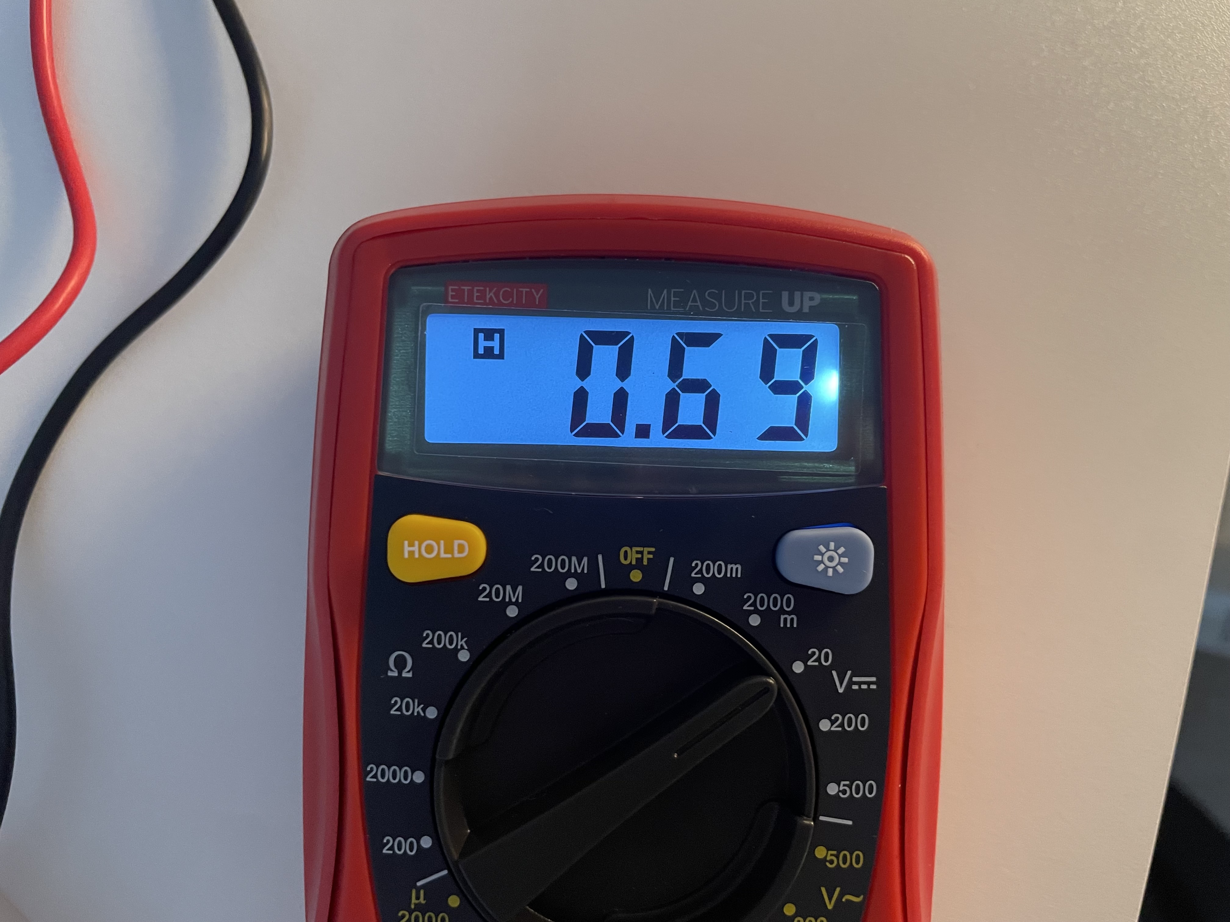
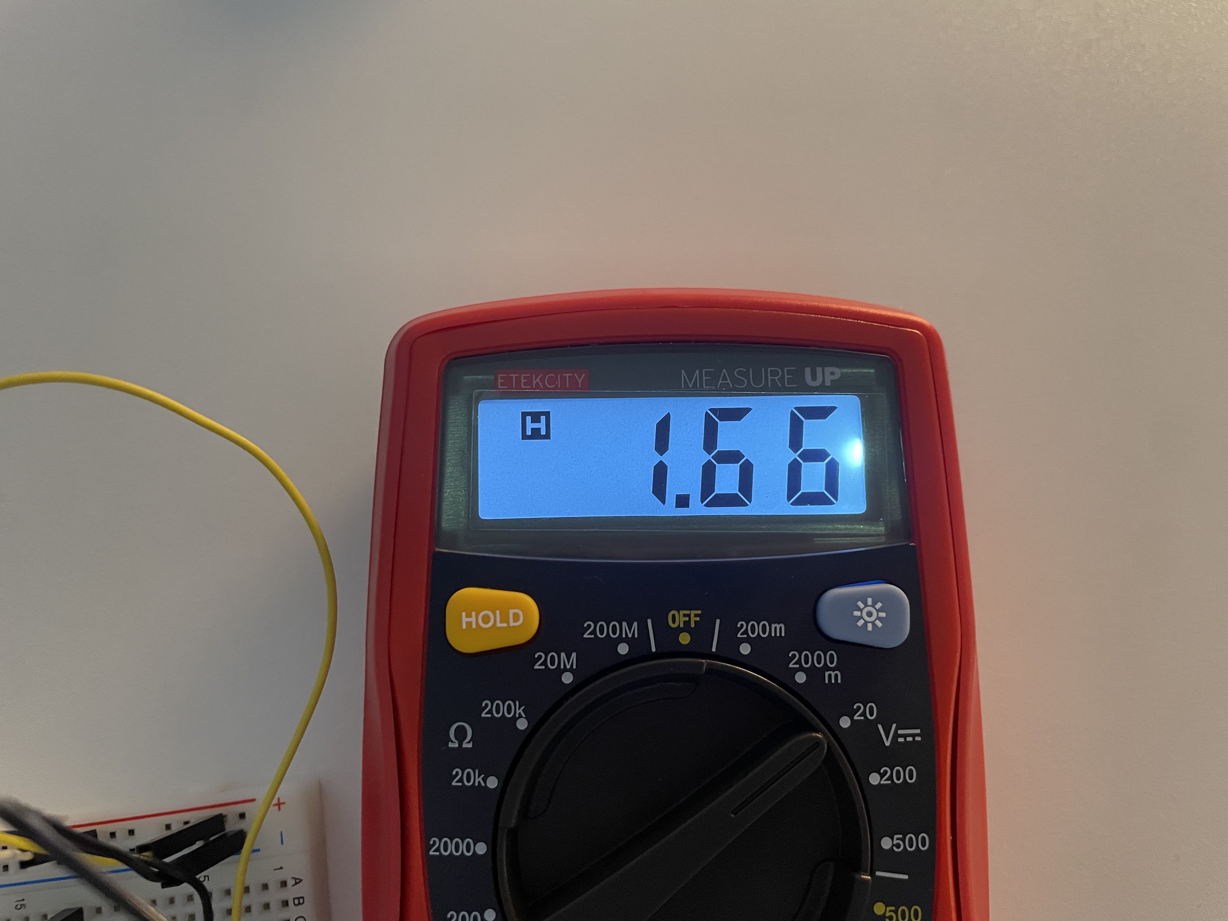
0.69V : voltage measure of resistor / 1.66V : voltage measured of led / 4.35V : voltage measured across a whole circuit (2V loss)
Ideally, these should add up exactly, but in practice some energy is lost as heat, light, or contact resistance.
*3 LED lights in series
It worked in series of 2 led light bulb with 5V but starting from 3 LEDs, the light would not turn on.
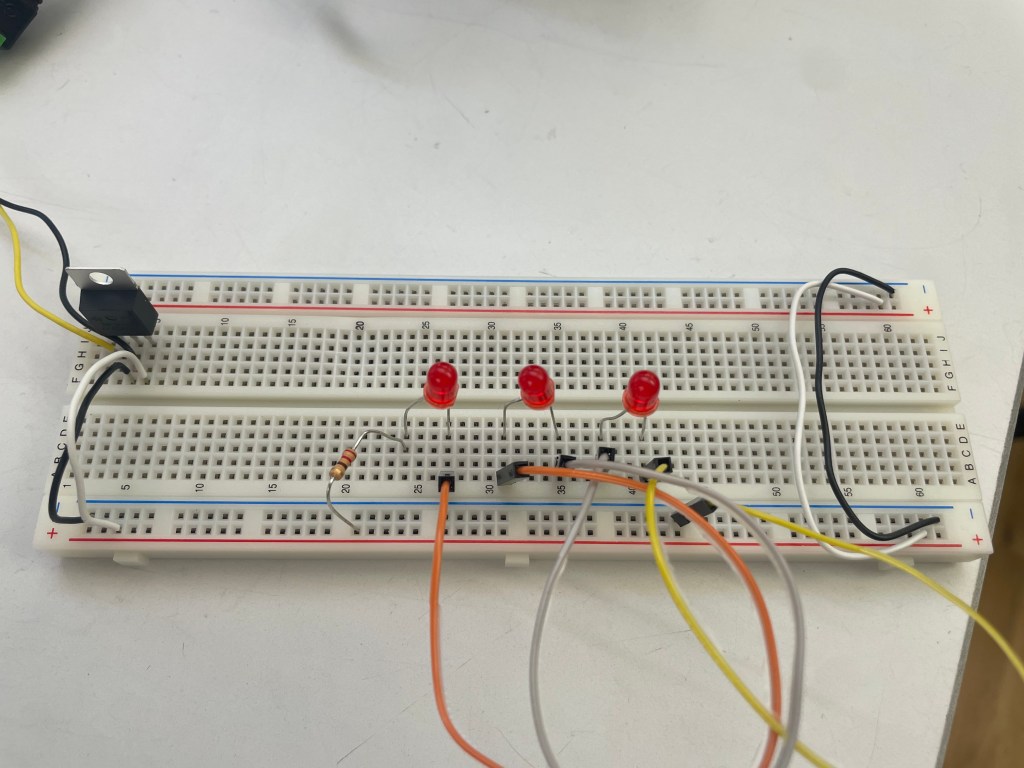
After switching dc power supply to 12V, three LEDs in series lit up but they were very dim.
- Component in Parallel
Voltage across the 3 led lights: 13.5V / Amperage: 0.6A (All the measurements were identical across the lights)
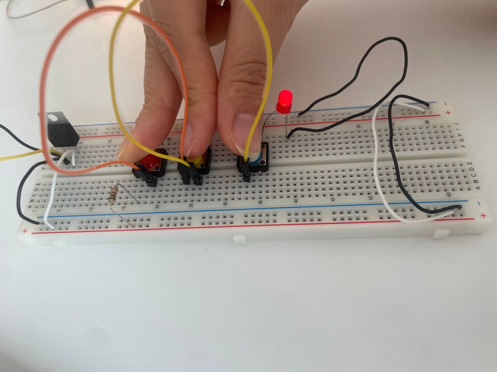
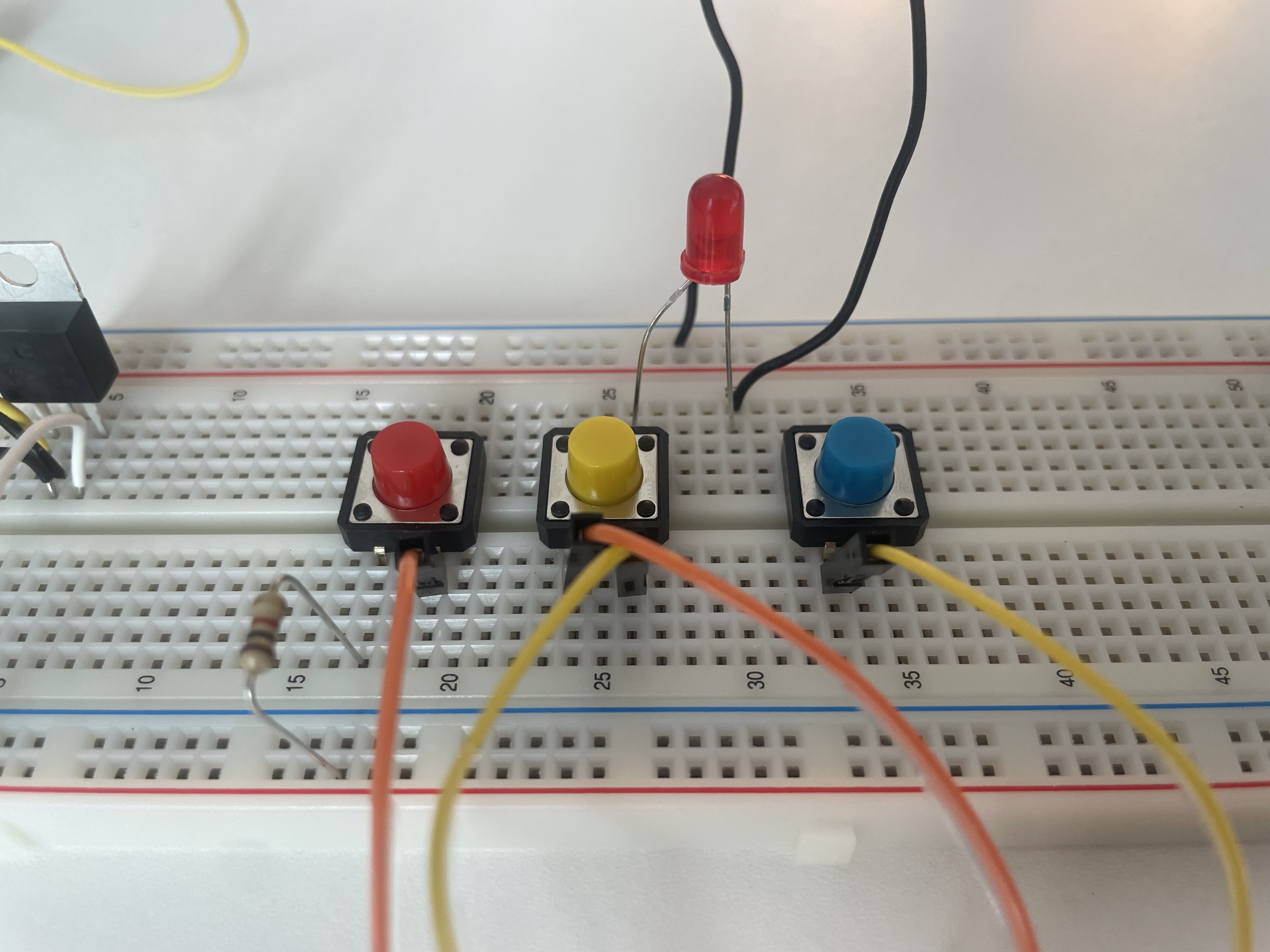
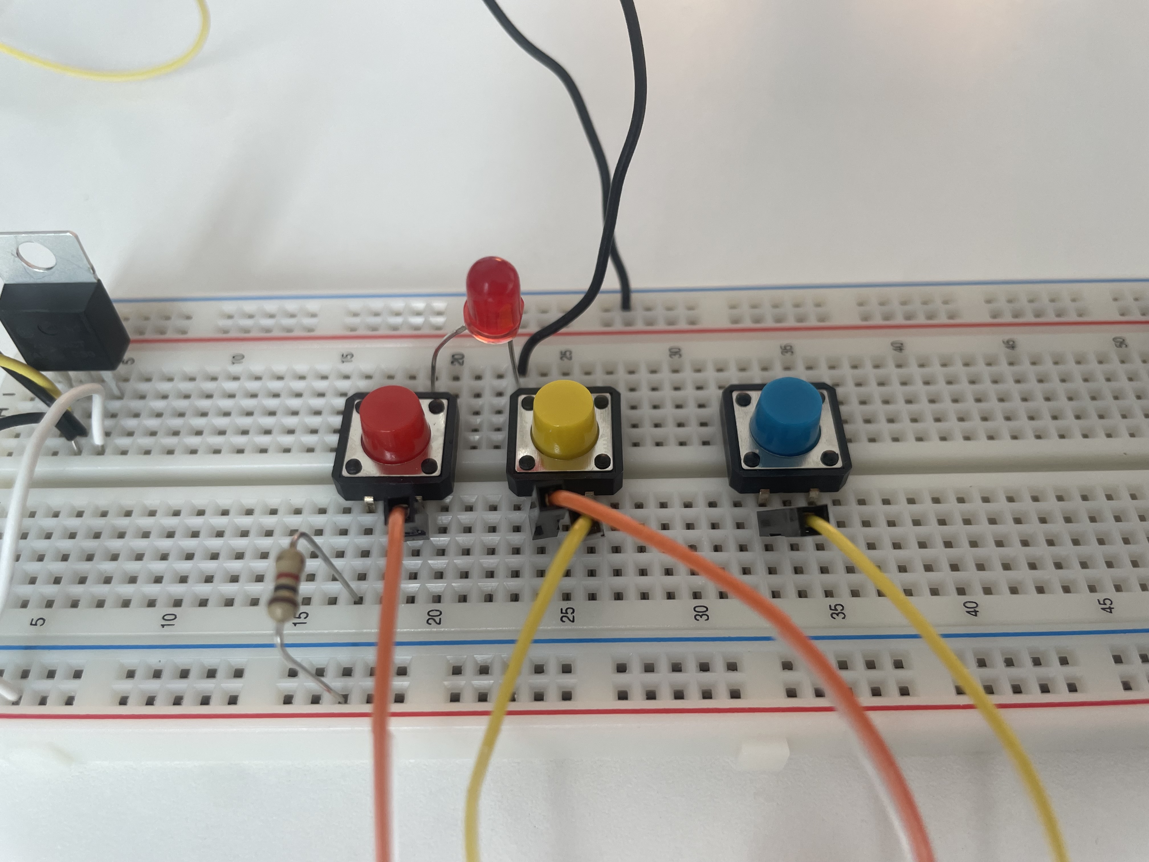
- Switches in Parallel
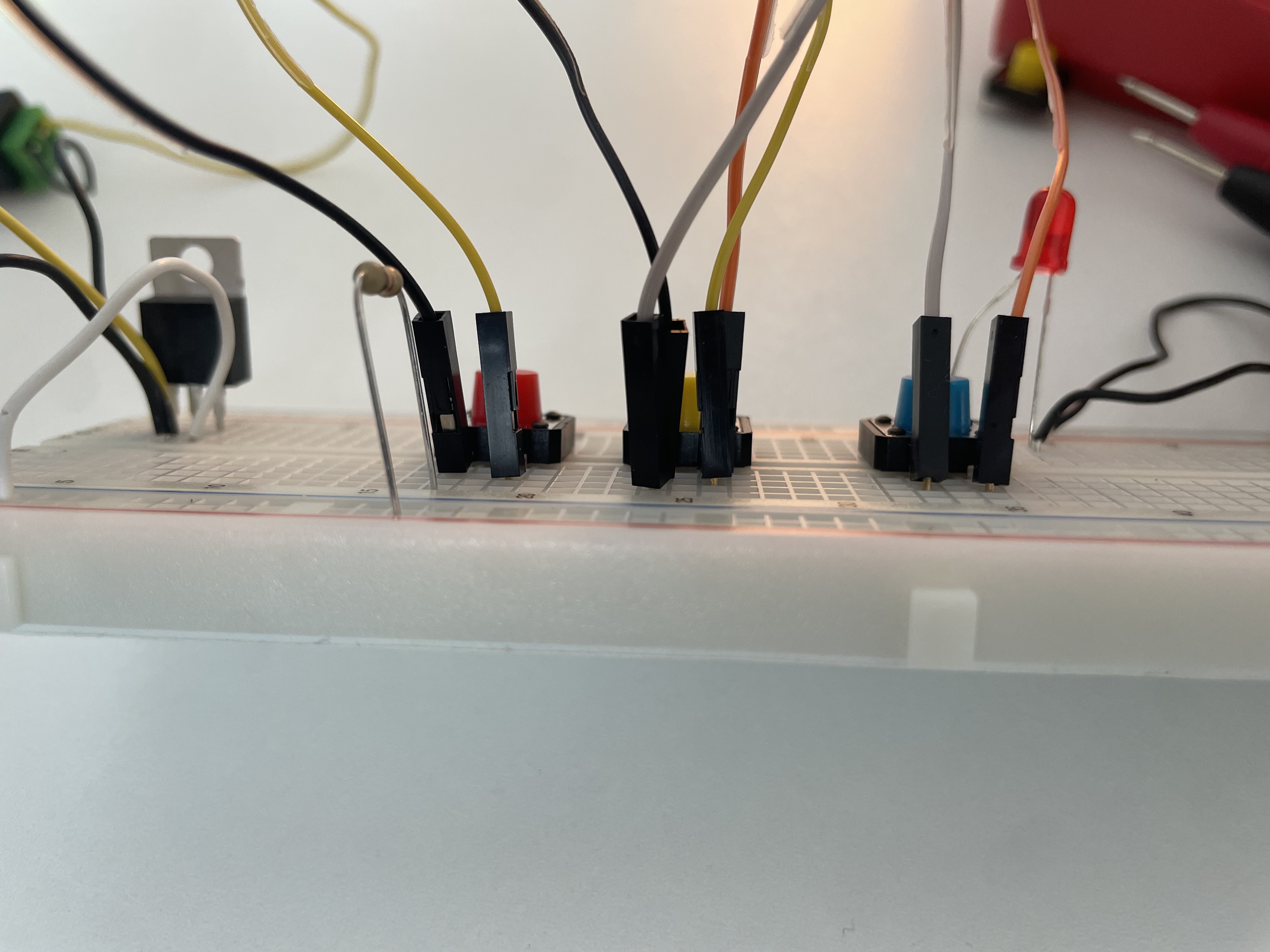
First trial : While two other switches worked well, the last one(blue) failed to turn on the LED. I tested the continuity with a multimeter, and all of the switches produced a beep when pressed. I also tested with another switch component, but it didn’t work either.
Second trial : I found that one of the wires between the second and third switches was placed in the wrong row, so it wasn’t actually connected to the switch. After I put wires in a correct place, all the switches worked well.
In a parallel configuration, the LED turns on if any switch is pressed.
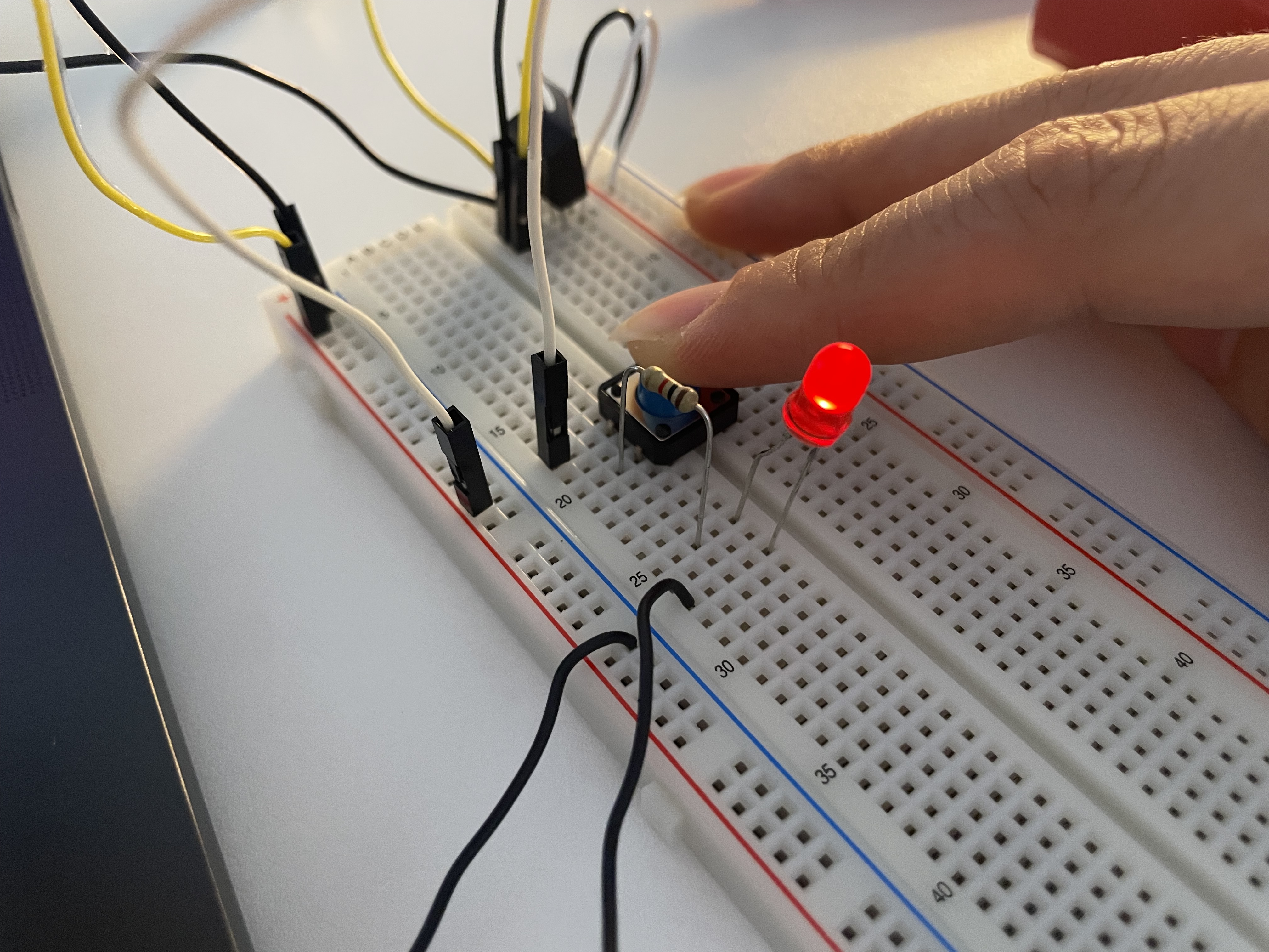
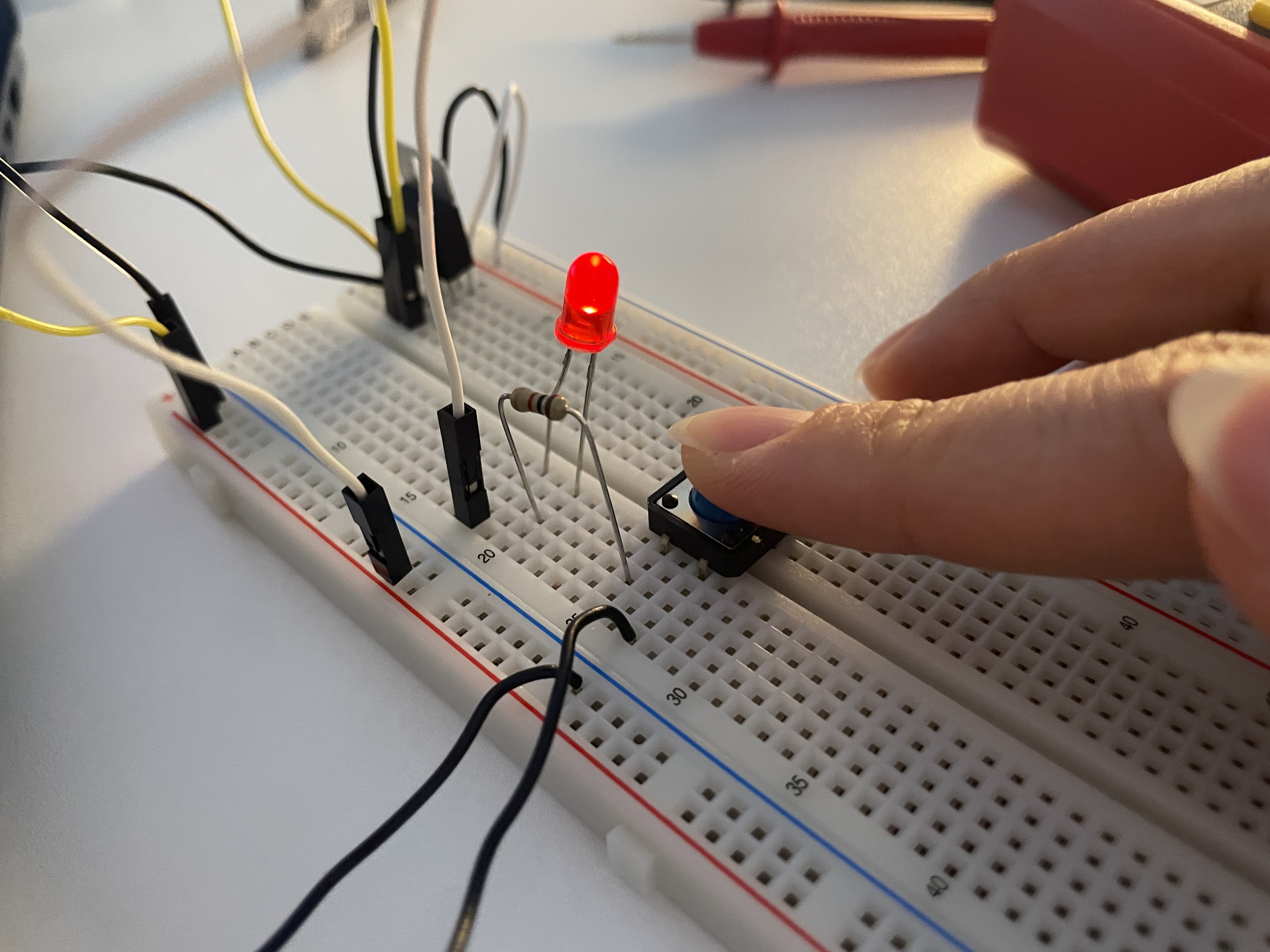
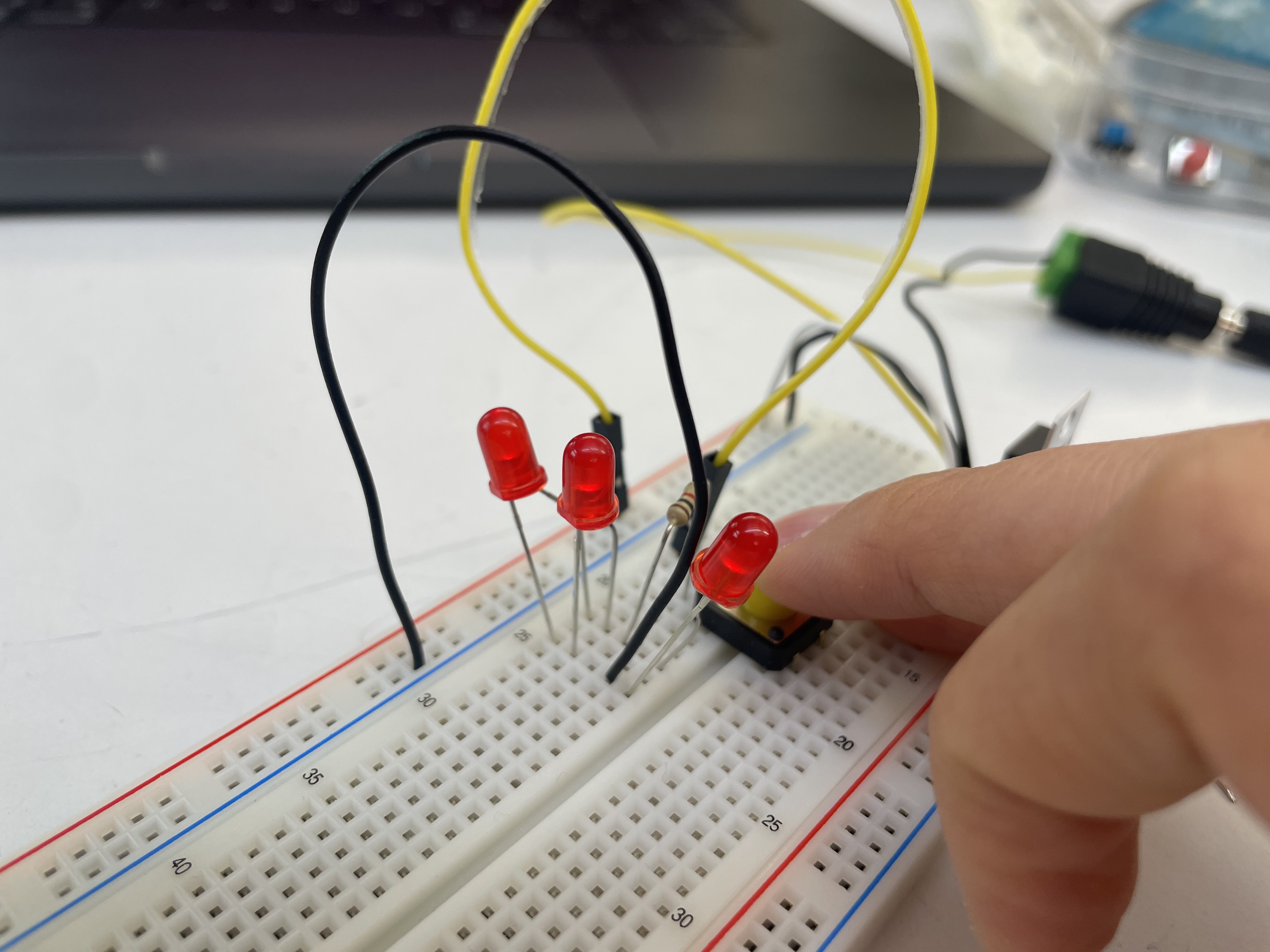
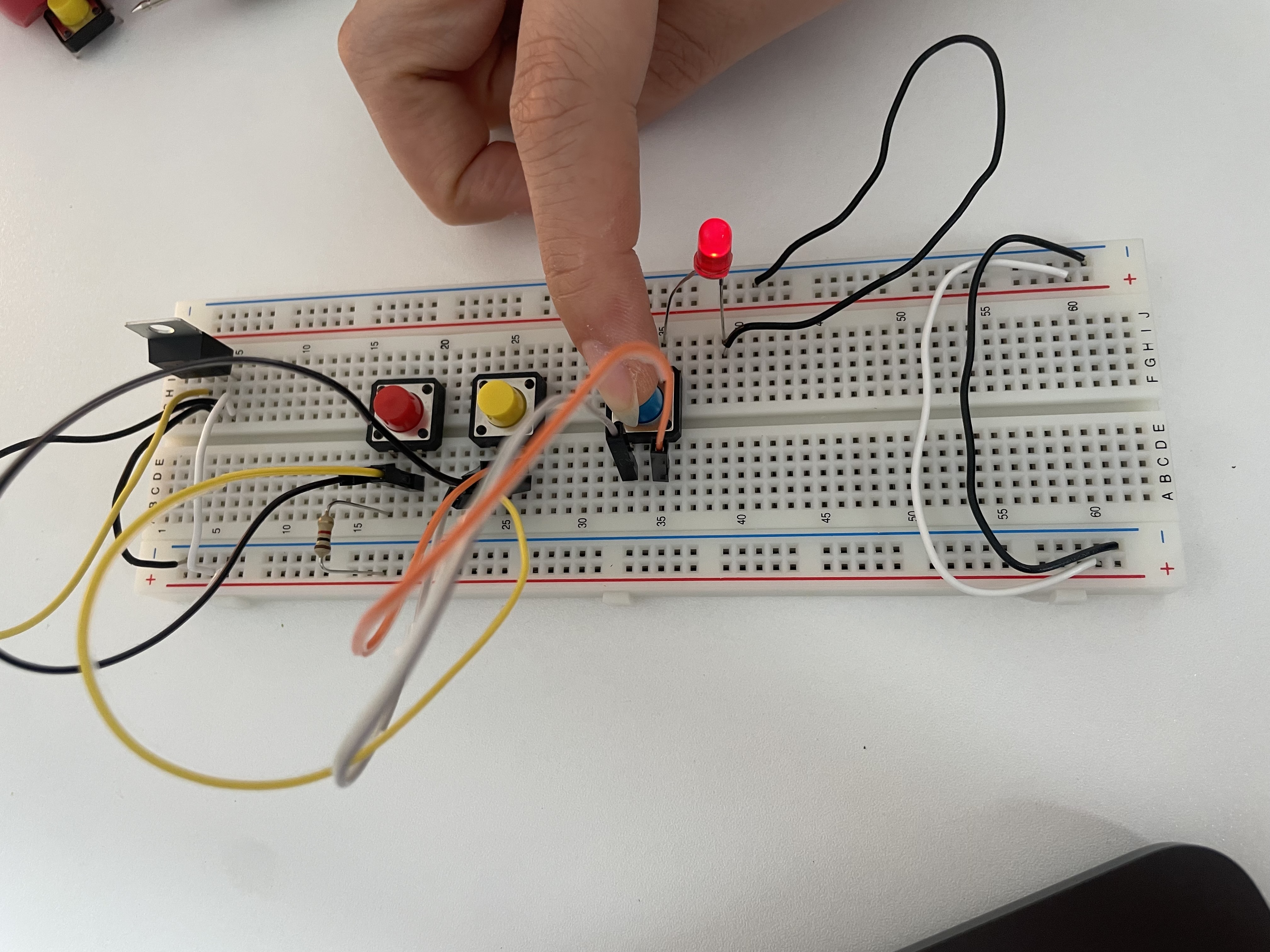
- Switches in Series
Three switches in series light up the LED only when all of them are pressed at the same time.💡
It worked the same after I changed the position of the LED. However, the circuit only worked correctly when the anode of the LED was not connected to the same row as the resistor. When the anode was in the same row as the resistor, the LED stayed on regardless of the switches.
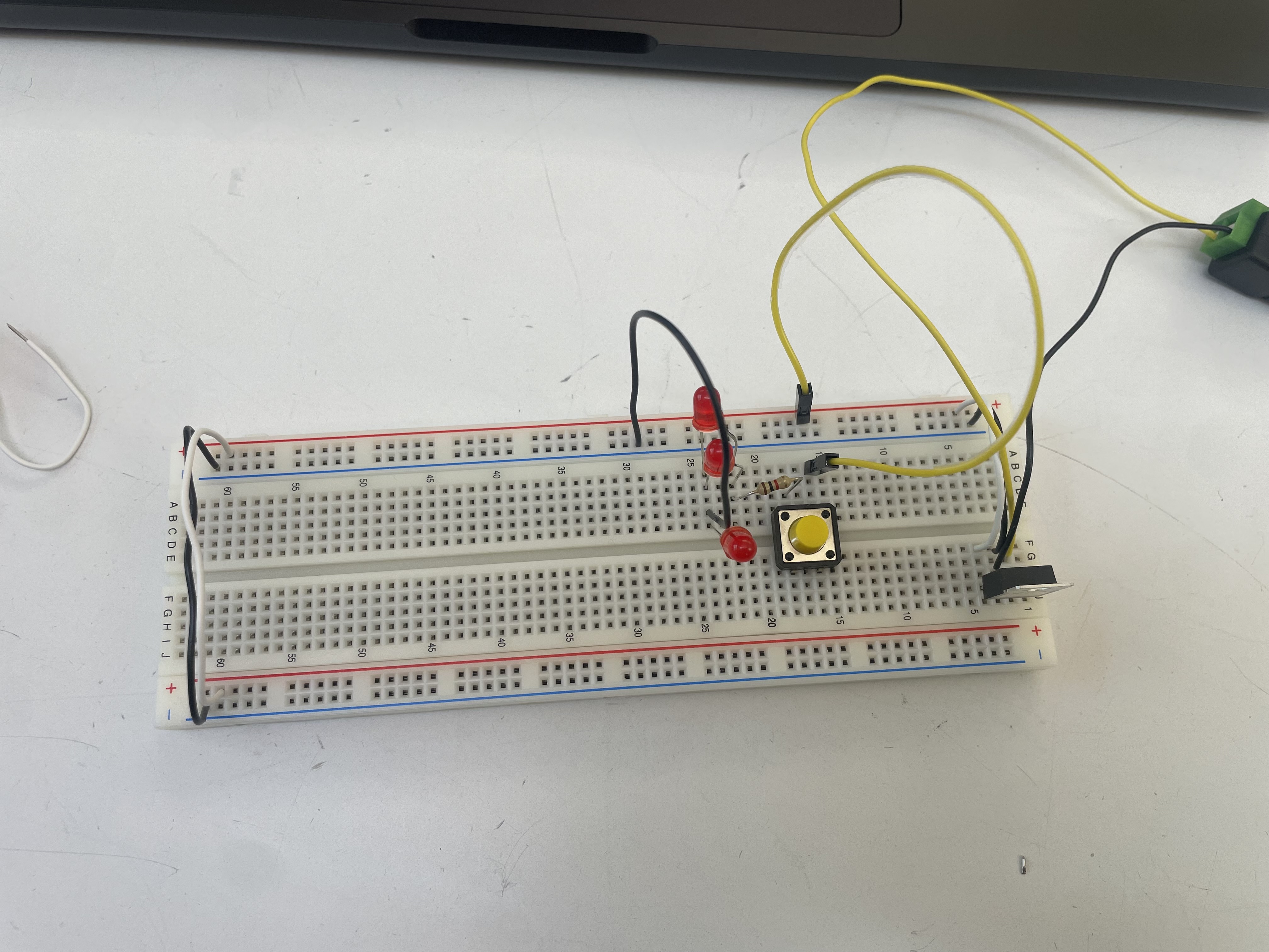
*Some experiments
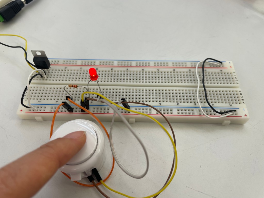
I found a push button switch that I wanted to experiment with. At first, I connected the switch wires directly to the voltage and ground bus. However, it worked in reverse — the LED stayed on and turned off when I pressed the button.
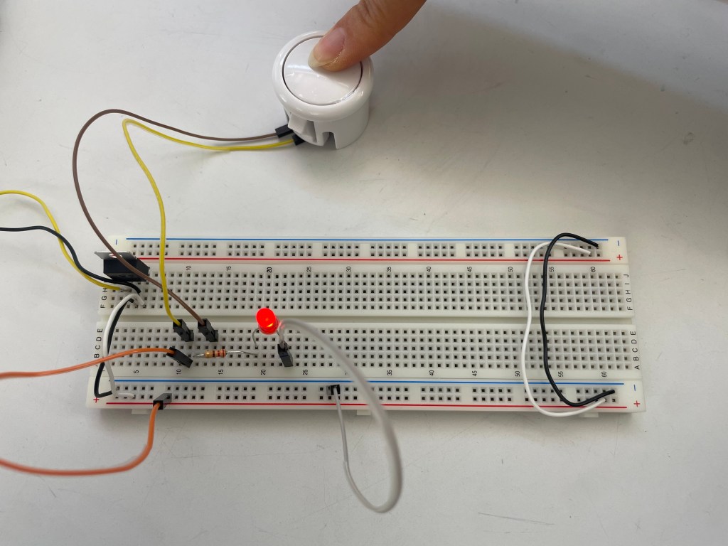
This worked in a proper way as I intented.
